How much load beam will sustain? This answer can be addresses by the bending stress. It relate the strength of material with moment.

In the park near your home, you might have seen the sea saw. Kids enjoy playing with this. But what happens when adults ride on it? It fails. What leads to this failure? Why do most of the bridges you have seen have a beam of shape? Is it aesthetically useful, or do they have some different purpose? To understand this, we need to discuss the bending of the beam.
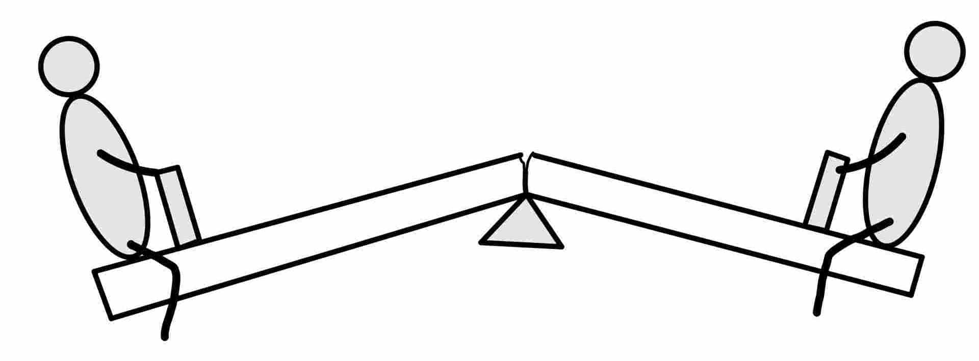
The members that resist the load by bending we call beams. When adults with more than recommended weight ride on the sea saw, they apply more bending moment it the rod. This bending moment leads to the bending stress in the beam. To know this thing in detail, let's discuss everything individually. In this, we will define the bending stress, derive the bending stress, discuss its limitation and see the application of the bending stress concept.
The moment due to transverse load in the beam causes the bending is called the bending moment. The stress in the beam due to this bending moment is called bending stress. We can define the bending moment as follows,
“It is the summation of all the moments either left or right of the section. “
This bending moment in the beam causes bending or flexure stresses. The formula for the relation between bending moment and bending or flexure stress is called the flexure formula.
You know, when we talk about the derivation, we need need to discuss the limitations of that derivation.
This formulation has the following assumptions
Shear stress: The plane section of the beam remains the plane after bending. Hence, there is no shear stress in the beam.
Homogenous: This formulation assumes that the material is homogeneous and obeys Hooke’s law.
Elastic Modulus: The modulus of elasticity of the beam is equal in tension and compression.
Prismatic section: The beam is initially straight and of a constant cross-section.
Pure bending: The loading plane must contain a principal axis of the beam cross-section, and the loads must be perpendicular to the longitudinal axis of the beam.
Don’t panic; we will discuss the application of the assumptions when and where the need arises.
This may appear very clumsy; you follow the step-by-step as we go through the step. We promise you that you will master the bending stress in one go.
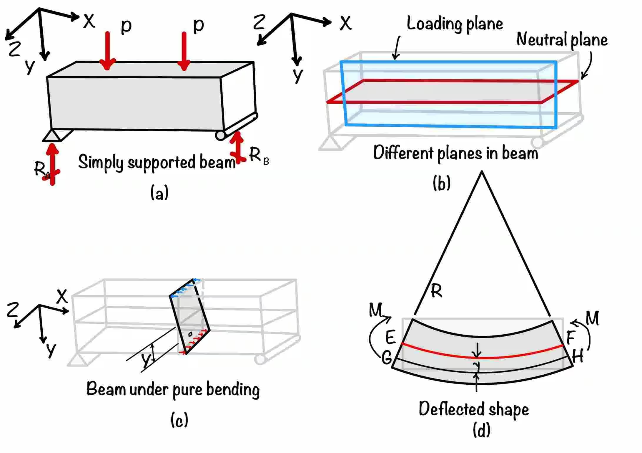
Part (a) of the figure shows the simply supported beam subjected to the point load, (b) shows the different planes, (c) bending stress developed in the beam, and (d) shows the deflected shape of the beam.
See part A of the figure. This figure shows the three-dimensional beam subjected to a transverse load.
The plane on which the load is acting is the loading plane. To resist the load beam starts bending. The plane and will bend, as shown in the figure. This plane will bend but not distort; this is due to assumption 1.
Due to this bending top fiber of the beam shortens, and the bottom fibers elongate. You can locate the fiber somewhere between them, which will not change the length. This fiber is called a neutral line and is in the three-dimensional neutral plane, as shown in part 2 of the figure.
Now consider the fiber at a distance from the neutral axis. Strain in this fiber is given by
Hence stress at a distance from the neutral axis
Where is the curvature of the neutral axis.
In the next step, connect the moment with the internal forces. Refer the part 3 of the figure. This figure shows the element at a distance from the neutral axis. Assume the area of the element is . Now the moment due to this element will be:
As we know, the second term on the right-hand side of the equation is the second moment of inertia.
Hence the above relation can be rewritten as :
Now from the above two relations, we can finally write the pure bending formula.
In the above section, we have discussed the neutral plane and neutral axis. It is the axis where stress is zero. Hence by using this property, we can find the location of the neutral axis in the section.
Substituting the value of into the equation, we will get
As can not be zero, the is the distance of the centroid from the neutral axis, = 0 means the neutral axis coincides with the centroidal axis.
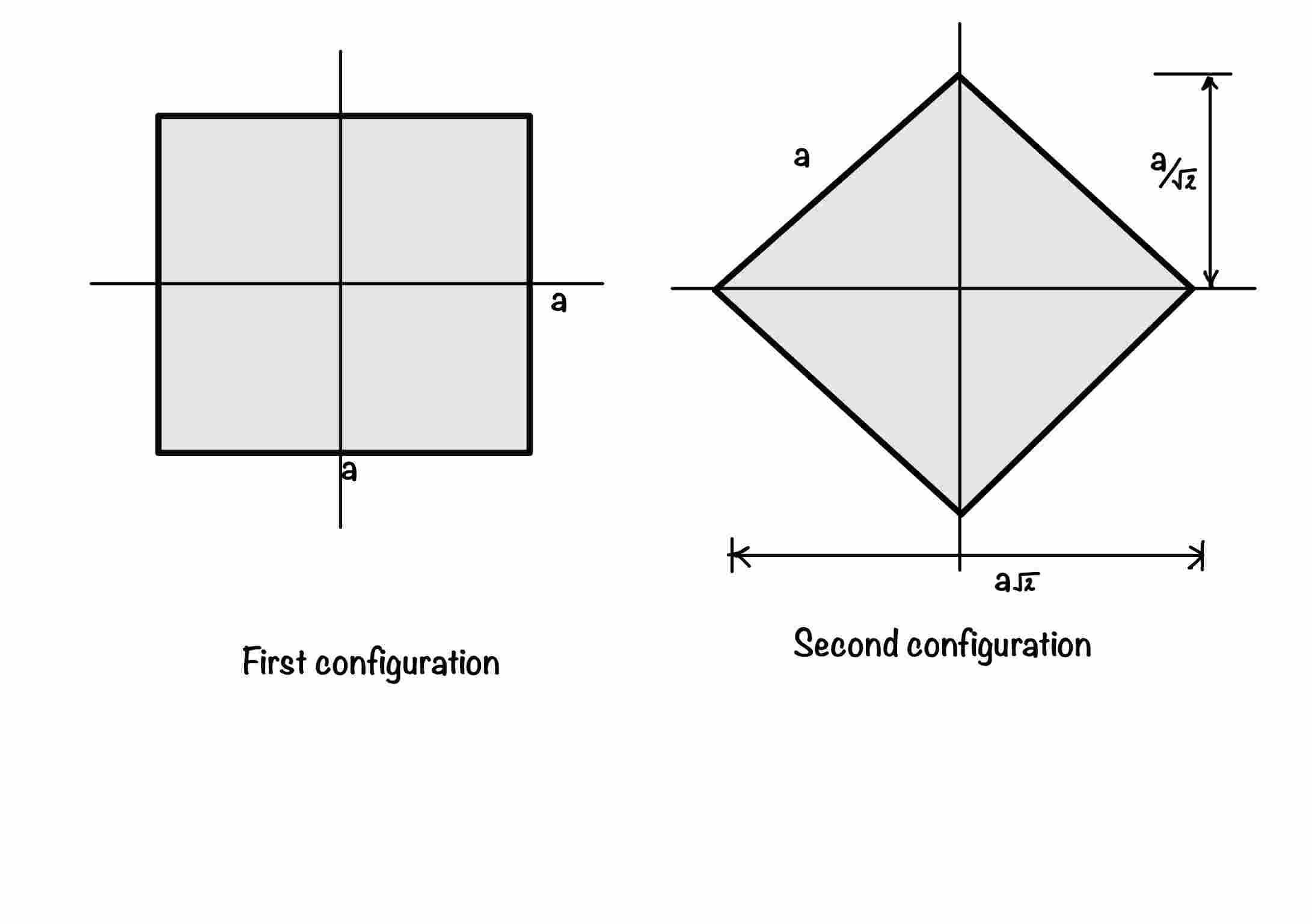
Now from the above formulation, you can find which section is more suitable for you. Let’s have one beam which has a square cross-section. Now you have two options to use the beam as shown in the figure.
How to decide which one is better for you?
To do that, let’s visit the bending formula again
Where is called the section modulus, for the same material, will be the same, as they will have the same strength. The moment-taking capacity will depend on the section modulus .
So for the above two conditions, the section with more should be your choice.
Let's calculate the section modulus
For case 2, and , substituting this values in the above equation to calculate .
Hence, arrangement (1) is stronger than arrangement (2).
To make large, we try to keep material away from the neutral axis, which results in section. This is the reason why we use I section beam most of the times.
The bending moment creates bending stress in the beam. While deriving the bending stress in the beam, we assumed that there was only pure bending. Is this assumption will work in real life? How the shear force will create shear stress in the beam.
In this post, you have learned the following key points:
Pure Bending Formula: The pure bending formula is .
Section Modulus: Section modulus is the key factor that decides which section will be more beneficial as a beam.
Your trusted source for breaking down core engineering concepts using first-principles thinking.